联系我们
与泰克代表实时聊天。 工作时间:上午 9:00 - 下午 5:00(太平洋标准时间)。
致电我们
工作时间:上午9:00-下午5:00(太平洋标准时间)
下载
下载手册、产品技术资料、软件等:
反馈
TPP0850 User Manual
These instructions describe the setup and basic operation of the TPP0850 and related accessories.
此手册适用于:
TPP0850
By downloading, you agree to the terms and conditions of the Manuals Download Agreement.
Manuals Download Agreement
ATTENTION: please read the following terms and conditions carefully before downloading any documents from this website. By downloading manuals from Tektronix' website, you agree to the following terms and conditions:
Manuals for Products That Are Currently Supported:
Tektronix hereby grants permission and license to owners of Tektronix instruments to download and reproduce the manuals on this website for their own internal or personal use. Manuals for currently supported products may not be reproduced for distribution to others unless specifically authorized in writing by Tektronix, Inc.
A Tektronix manual may have been revised to reflect changes made to the product during its manufacturing life. Thus, different versions of a manual may exist for any given product. Care should be taken to ensure that one obtains the proper manual version for a specific product serial number.
Manuals for Products That Are No Longer Supported:
Tektronix cannot provide manuals for measurement products that are no longer eligible for long term support. Tektronix hereby grants permission and license for others to reproduce and distribute copies of any Tektronix measurement product manual, including user manuals, operator's manuals, service manuals, and the like, that (a) have a Tektronix Part Number and (b) are for a measurement product that is no longer supported by Tektronix.
A Tektronix manual may be revised to reflect changes made to the product during its manufacturing life. Thus, different versions of a manual may exist for any given product. Care should be taken to ensure that one obtains the proper manual version for a specific product serial number.
This permission and license does not apply to any manual or other publication that is still available from Tektronix, or to any manual or other publication for a video production product or a color printer product.
Disclaimer:
Tektronix does not warrant the accuracy or completeness of the information, text, graphics, schematics, parts lists, or other material contained within any measurement product manual or other publication that is not supplied by Tektronix or that is produced or distributed in accordance with the permission and license set forth above.
Tektronix may make changes to the content of this website or to its products at any time without notice.
Limitation of Liability:
TEKTRONIX SHALL NOT BE LIABLE FOR ANY DAMAGES WHATSOEVER (INCLUDING, WITHOUT LIMITATION, ANY CONSEQUENTIAL OR INCIDENTAL DAMAGES, DAMAGES FOR LOSS OF PROFITS, BUSINESS INTERRUPTION, OR FOR INFRINGEMENT OF INTELLECTUAL PROPERTY) ARISING OUT OF THE USE OF ANY MEASUREMENT PRODUCT MANUAL OR OTHER PUBLICATION PRODUCED OR DISTRIBUTED IN ACCORDANCE WITH THE PERMISSION AND LICENSE SET FORTH ABOVE.
Read Online
Operating information
The TPP0850 Probe is a high impedance probe with 50X attenuation that is designed for use with Tektronix 4/5/6 Series Mixed Signal Oscilloscopes.
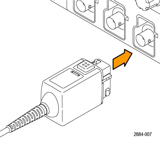
Connect the probe as shown in the illustrations below. Compensate the probe before initial use.
Compensate the TPP Series probes
Probe compensation adjusts the high frequency response of a probe for best waveform capture and measurement accuracy. The oscilloscope can automatically test and store compensation values for an unlimited number of probe/channel combinations.
About this task
The oscilloscope stores the compensation values for each probe/channel combination, and automatically recalls the compensation values when you plug in the probe. Probe compensation status is shown in the Probe Setup panel of the Channel configuration menu.
- If the Probe Compensation Status field displays Pass, the probe is compensated and ready for use.
- If the Probe Compensation Status field displays Default, the attached probe has not been compensated and needs to have this probe compensation procedure run.
- If the Probe Compensation Status field displays Fail, the attached probe has failed the probe compensation procedure. Reconnect the probe and run probe compensation again.
- If there is no probe compensation status field shown in the panel, the oscilloscope cannot store compensation values for that probe. See the oscilloscope Help for how to manually compensate passive probes not supported by the probe compensation function.
Before you begin
The oscilloscope must be powered on for at least 20 minutes before compensating a probe.
Procedure
 | Note:Doing a Default Setup does not delete probe compensation values. A factory calibration does delete all stored probe compensation values. |
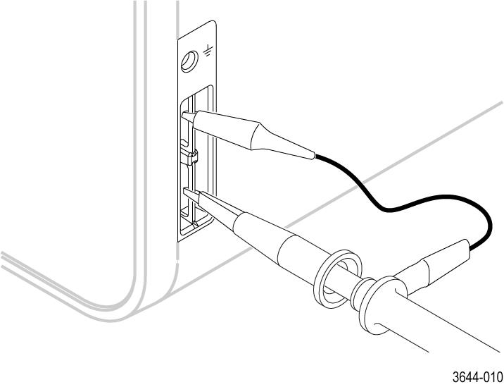
- Connect the probe tip and ground lead of the probe to the PROBE COMP terminals.
 Note:Connect only one probe at a time to the PROBE COMP terminals.
 - Repeat these steps to compensate supported probes on other channels of the oscilloscope.Note:For most accurate measurements, open the Probe Setup panel and verify the Probe Compensation Status is Pass whenever you attach a probe to a channel.
Standard accessories
| WARNING:Do not substitute accessories from other products for use with this probe. Only use the accessories that are included with this probe. |
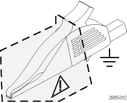
| WARNING:To avoid electric shock when using the probe or accessories, keep your fingers behind the finger guard of the probe body and away from the shaded area shown in the accessory illustrations below. |
| Item | Description | ||
|---|---|---|---|
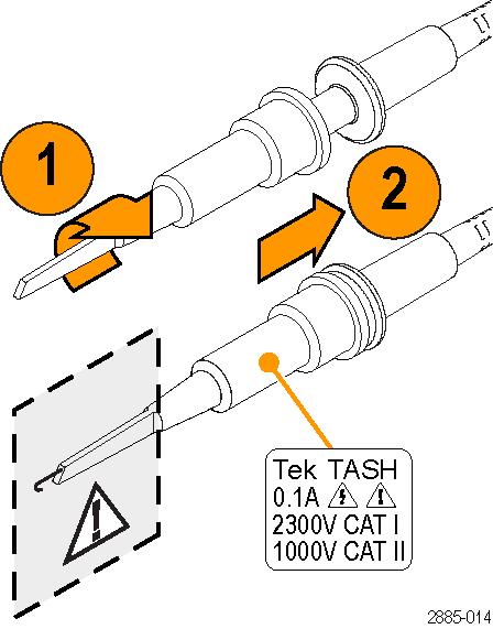 |
Small hook tip (TASH) Use this tip to access test points in tight spaces. Screw the hook tip onto the probe tip and then clamp the hook onto the circuit. Rating: 1000 V CAT II. Only the 1000 V CAT II rating is applicable when used with the TPP0850 probe. Tektronix part number 013-0388-XX | ||
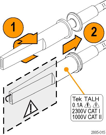 |
Large hook tip (TALH) Screw the hook tip onto the probe tip and then clamp the hook onto the circuit. Rating: 1000 V CAT II. Only the 1000 V CAT II rating is applicable when used with the TPP0850 probe. Tektronix part number 013-0389-XX | ||
 |
Common leads (6 in and 18 in) (TACL) Slide the lead over the probe head and snap it into place. Connect the banana plug end directly to your circuit common, or use the crocodile clip included with the probe. Tektronix part numbers: 196-3526-XX (6 inch) and 196-3527-XX (18 inch) | ||
 |
Crocodile clip Attach the clip to the banana end of the common lead and then to your circuit common. Tektronix part number: 344-0461-XX | ||
|
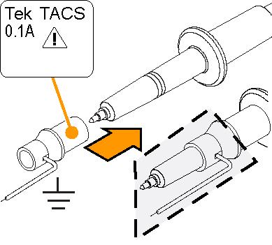
Common spring (TACS) Use this accessory to limit aberrations on high frequency signals caused by common lead path inductance. Bend the spring to reach nearby common connections (~1 in). Tektronix part number 214-5299-XX | ||
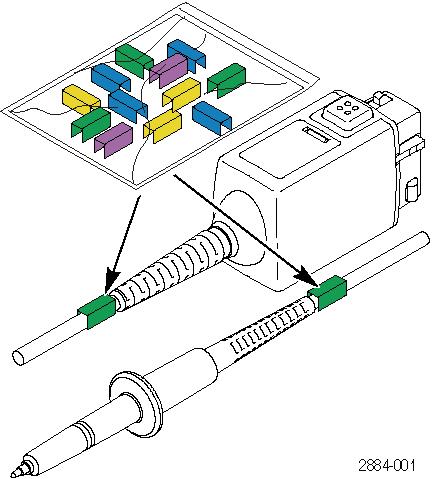 |
Color bands Use these bands to identify the oscilloscope channel at the probe head. Tektronix part number: 016-1886-XX (5 pairs) |
Optional accessories
The accessories shown below are available for the probes and are rated ≤30 V unless indicated otherwise.
| Accessory | Part number | |
|---|---|---|
| BNC to Tip Adapter, Unterminated |
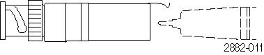 | 013-0291-XX |
| Rubber Spring Tip |
 | 206-0060-XX |
| Probe Holder |
 | TPH1000 |
Specifications
| Electrical and mechanical specifications | |
|---|---|
| Bandwidth (–3 dB) | 800 MHz |
| System rise time (typical) | <525 ps |
| System input capacitance (typical) |
1.8 pF |
| System attenuation accuracy | 50:1 ±2.2% |
| System input resistance @DC | 40 MΩ ±1% |
| Propagation delay | ~6.1 ns |
| Cable length | 1.3 m |
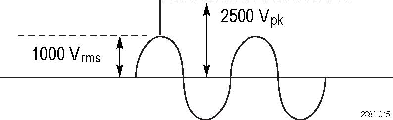
| Maximum input voltage (see Performance Graphs) | 1000 VRMS CAT II (2500 Vpk) |
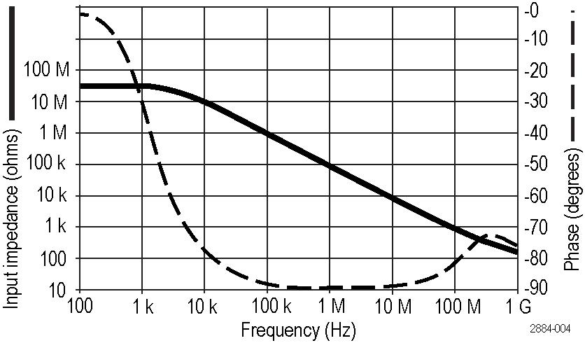
Performance graphs

| Environmental specifications | |
|---|---|
| Temperature | Operating: 0 °C to +50 °C (+32 °F to +122 °F) |
| Nonoperating: –40 °C to +71 °C (–40 °F to +160 °F) | |
| Humidity | Operating: 5% to 95% relative humidity (RH) up to +30 °C 5% to 75% RH above +30 °C to +50 °C. Noncondensing |
| Nonoperating: 5% to 45% RH +65 °C to +85 °C. Noncondensing | |
| Altitude | Operating: 3.0 km (9,842 ft) maximum |
| Nonoperating: 15.4 km (50,000 ft) maximum | |
Safety compliance
This section lists the safety standards with which the product complies and other safety compliance information.
EU declaration of conformity – low voltage
Compliance was demonstrated to the following specification as listed in the Official Journal of the European Union:
Low Voltage Directive 2014/35/EU.
- EN 61010-031. Particular requirements for handheld probe assemblies for electrical measurement and test equipment
U.S. nationally recognized testing laboratory listing
- UL 61010-031. Particular requirements for handheld probe assemblies for electrical measurement and test equipment
Canadian certification
- CAN/CSA-C22.2 No. 61010-031. Particular requirements for handheld probe assemblies for electrical measurement and test equipment
Additional compliances
- IEC 61010-031. Particular requirements for handheld probe assemblies for electrical measurement and test equipment
Pollution degree description
A measure of the contaminants that could occur in the environment around and within a product. Typically the internal environment inside a product is considered to be the same as the external. Products should be used only in the environment for which they are rated.
- Pollution Degree 1. No pollution or only dry, nonconductive pollution occurs. Products in this category are generally encapsulated, hermetically sealed, or located in clean rooms.
- Pollution Degree 2. Normally only dry, nonconductive pollution occurs. Occasionally a temporary conductivity that is caused by condensation must be expected. This location is a typical office/home environment. Temporary condensation occurs only when the product is out of service.
- Pollution Degree 3. Conductive pollution, or dry, nonconductive pollution that becomes conductive due to condensation. These are sheltered locations where neither temperature nor humidity is controlled. The area is protected from direct sunshine, rain, or direct wind.
- Pollution Degree 4. Pollution that generates persistent conductivity through conductive dust, rain, or snow. Typical outdoor locations.
Pollution degree rating
Pollution Degree 2
Measurement and overvoltage category descriptions
Measurement terminals on this product may be rated for measuring mains voltages from one or more of the following categories (see specific ratings marked on the product and in the manual).
- Overvoltage Category I. For equipment intended to be connected to a mains supply in which means have been taken to substantially and reliably reduce transient overvoltages to a level where they cannot cause a hazard.
- Measurement Category II. For measurements performed on circuits directly connected to the low-voltage installation.
- Measurement Category III. For measurements performed in the building installation.
- Measurement Category IV. For measurements performed at the source of low-voltage installation.
| Note:Only mains power supply circuits have an overvoltage category rating. Only
measurement circuits have a measurement category rating. Other circuits within the
product do not have either rating. |
Environmental compliance
This section provides information about the environmental impact of the product.
 |
This symbol indicates that this product complies with the applicable European Union requirements according to Directives 2012/19/EU and 2006/66/EC on waste electrical and electronic equipment (WEEE) and batteries. For information about recycling options, check the Tektronix Web site (http://www.tek.com/productrecycling). |
Important safety information
This manual contains information and warnings that must be followed by the user for safe operation and to keep the product in a safe condition.
To avoid fire or personal injury
Connect and disconnect properly
Do not connect or disconnect probes or test leads while they are connected to a voltage source.
Use only insulated voltage probes, test leads, and adapters supplied with the product, or indicated by Tektronix to be suitable for the product.
Connect the probe output to the measurement instrument before connecting the probe to the circuit under test. Connect the probe reference lead to the circuit under test before connecting the probe input. Disconnect the probe input and the probe reference lead from the circuit under test before disconnecting the probe from the measurement instrument.
De-energize the circuit under test before connecting or disconnecting the current probe.
Observe all terminal ratings
To avoid fire or shock hazard, observe all rating and markings on the product. Consult the product manual for further ratings information before making connections to the product.
Do not exceed the Measurement Category (CAT) rating and voltage or current rating of the lowest rated individual component of a product, probe, or accessory. Use caution when using 1:1 test leads because the probe tip voltage is directly transmitted to the product.
Do not apply a potential to any terminal, including the common terminal, that exceeds the maximum rating of that terminal.
Do not float the common terminal above the rated voltage for that terminal.
The measurement terminals on this product are not rated for connection to Category III or IV circuits.
Do not connect a current probe to any wire that carries voltages above the current probe voltage rating.
Do not operate without covers
Do not operate this product with covers or panels removed, or with the case open. Hazardous voltage exposure is possible.
Avoid exposed circuitry
Do not touch exposed connections and components when power is present.
Do not operate with suspected failures
If you suspect that there is damage to this product, have it inspected by qualified service personnel.
Disable the product if it is damaged. Do not use the product if it is damaged or operates incorrectly. If in doubt about safety of the product, turn it off and disconnect the power cord. Clearly mark the product to prevent its further operation.
Before use, inspect voltage probes, test leads, and accessories for mechanical damage and replace when damaged. Do not use probes or test leads if they are damaged, if there is exposed metal, or if a wear indicator shows.
Examine the exterior of the product before you use it. Look for cracks or missing pieces.
Use only specified replacement parts.
Wear eye protection
Wear eye protection if exposure to high-intensity rays or laser radiation exists.
Do not operate in wet/damp conditions
Be aware that condensation may occur if a unit is moved from a cold to a warm environment.
Do not operate in an explosive atmosphere
Keep product surfaces clean and dry
Remove the input signals before you clean the product.
Provide a safe working environment
Always place the product in a location convenient for viewing the display and indicators.
Avoid improper or prolonged use of keyboards, pointers, and button pads. Improper or prolonged keyboard or pointer use may result in serious injury.
Be sure your work area meets applicable ergonomic standards. Consult with an ergonomics professional to avoid stress injuries.
Use care when lifting and carrying the product. This product is provided with a handle or handles for lifting and carrying.
| WARNING:The product is heavy. To reduce the risk of personal injury or damage to the device get help when lifting or carrying the product. |
| WARNING:The product is heavy. Use a two-person lift or a mechanical aid. |
Use only the Tektronix rackmount hardware specified for this product.
Probes and test leads
Before connecting probes or test leads, connect the power cord from the power connector to a properly grounded power outlet.
Keep fingers behind the protective barrier, protective finger guard, or tactile indicator on the probes. Remove all probes, test leads and accessories that are not in use.
Use only correct Measurement Category (CAT), voltage, temperature, altitude, and amperage rated probes, test leads, and adapters for any measurement.
Beware of high voltages
Understand the voltage ratings for the probe you are using and do not exceed those ratings. Two ratings are important to know and understand:
- The maximum measurement voltage from the probe tip to the probe reference lead.
- The maximum floating voltage from the probe reference lead to earth ground.
These two voltage ratings depend on the probe and your application. Refer to the Specifications section of the manual for more information.
| WARNING:To prevent electrical shock, do not exceed the maximum measurement or maximum floating voltage for the oscilloscope input BNC connector, probe tip, or probe reference lead. |
Connect and disconnect properly.
Connect the probe output to the measurement product before connecting the probe to the circuit under test. Connect the probe reference lead to the circuit under test before connecting the probe input. Disconnect the probe input and the probe reference lead from the circuit under test before disconnecting the probe from the measurement product.
De-energize the circuit under test before connecting or disconnecting the current probe.
Connect the probe reference lead to earth ground only.
Do not connect a current probe to any wire that carries voltages or frequencies above the current probe voltage rating.
Inspect the probe and accessories
Before each use, inspect probe and accessories for damage (cuts, tears, or defects in the probe body, accessories, or cable jacket). Do not use if damaged.
Ground-referenced oscilloscope use
Do not float the reference lead of this probe when using with ground-referenced oscilloscopes. The reference lead must be connected to earth potential (0 V).
Floating measurement use
Do not float the reference lead of this probe above the rated float voltage.
Terms in this manual
These terms may appear in this manual:
| WARNING:Warning statements identify conditions or practices that could result in injury or loss of life. |
| CAUTION:Caution statements identify conditions or practices that could result in damage to this product or other property. |
Terms on the product
These terms may appear on the product:
- DANGER indicates an injury hazard immediately accessible as you read the marking.
- WARNING indicates an injury hazard not immediately accessible as you read the marking.
- CAUTION indicates a hazard to property including the product.
Symbols on the product
 | When this symbol is marked on the product, be sure to consult the manual to find out the nature of the potential hazards and any actions which have to be taken to avoid them. (This symbol may also be used to refer the user to ratings in the manual.) |
The following symbols(s) may appear on the product.
 CAUTION: Refer to Manual |  Earth Terminal |
Help us improve our technical documentation. Provide feedback on our TekTalk documentation forum.