Introduction
Over the last few decades, a growing number of colleges and universities have revised their approach to laboratory teaching to help students get ready to face real-world electrical engineering challenges after graduation. As part of this process, instructors are updating many legacy lab experiments by incorporating the latest industrial applications. In this way, the method of managing a project in an industrial setting is also being applied in the project (student) laboratory. In addition, instructors have begun using industrial standards to evaluate their students’ designs.
When comparing the design mindsets of students with those of engineers, one of the biggest differences relates to design reliability. For students, the main objective is often to finish a design that meets the requirements of the assignment, but the design’s reliability is often a secondary consideration. In contrast, for engineers, reliability is the most critical aspect of the design, even more important than specifications in many circumstances, because reliability is among the main criteria used when customers make purchasing decisions. All specifications of the design must be tested in a temperature chamber over an extended period over its rated temperature ranges.
This application note describes how to use TekBench™ software and a Tek oscilloscope to perform measurement data logging for evaluating a design’s reliability in a roomtemperature environment, such as a project laboratory.
Preparation
- TekBench™ software
Visit www.tek.com/tekbench to download the TekBench software and install it on a laptop.* Apply a demo license, which can be accessed via the same page, to activate the software. Until the software is activated, the measurement data logging function can only take 30 minutes’ worth of data.
*Minimal operating requirements: Win7 or Win10, dual core 2 GHz CPU or above, 4 G DDR3 RAM or above, 1 GB free hard disk space, 1366×768 screen resolution or above, USB interface.
- Oscilloscope
The list of supported oscilloscopes can be found in the TekBench software under: About-> About. Here, the MDO3102 is used as an example.
- Circuit board
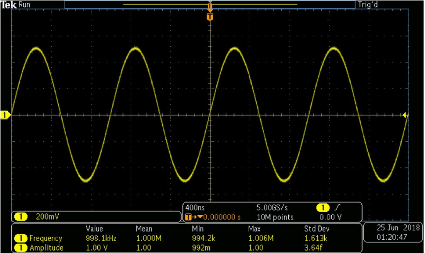
Use a circuit board that can output a Sine signal with 1 MHz frequency and 1 V amplitude
1. Connect the oscilloscope to the circuit board via a probe and adjust the parameters of the oscilloscope to take the measurement shown in Figure 1.
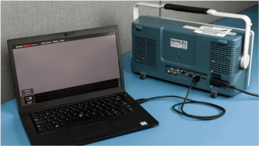
2. Open the TekBench application, then connect the oscilloscope to the laptop using a USB cable as shown in Figure 2. The application will detect the oscilloscope within a few seconds.
Configure measurement data logging
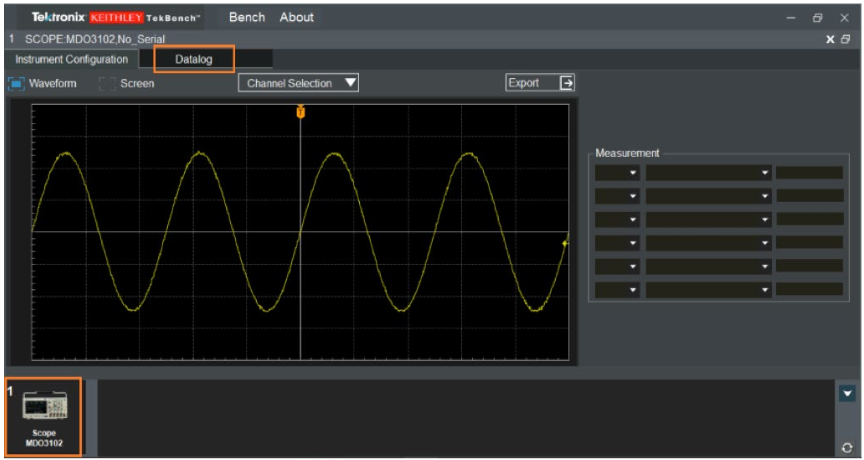
3. Double-click the oscilloscope icon to load it into the software application. Then click the Datalog tab to access the measurement data logging interface (Figure 3).
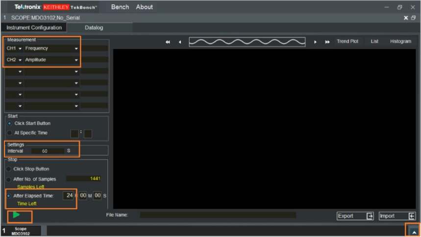
4. In the measurement data logging interface (Figure 4) click the arrow in the lower right corner to hide the instrument icon, then set up the measurement parameters as listed here:
Select measurement items:
CH1 Frequency and
CH1 Amplitude
Set measurement interval: 60 S
Set After Elapsed time: 24 Hours
Click the Start icon (the green arrow in Figure 4) to start measurement data logging; it will finish automatically after 24 hours.
Analyze the testing results
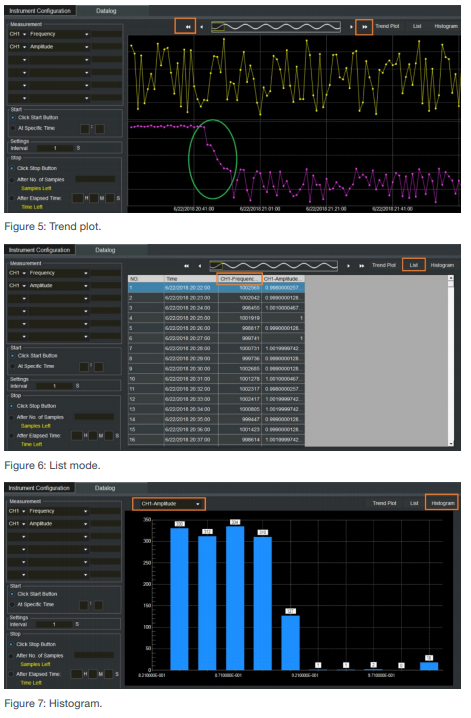
5. The TekBench application offers three ways to check the results.
-
Trend plot: Click the arrows to navigate the test results.
-
List mode: Scroll down to navigate the results or click measurement items to find the max/min value quickly.
-
Histogram: Check the distribution of the measurement results. As shown in Figure 7, most of the amplitude values are <0.92 V.
As illustrated in Figure 5, the Amplitude value (the purple line) decreased after working for around 30 minutes. This might be due to the poor temperature coefficient of the resistor used in the design.
6. Click Export to export the results into a *.csv file, then use Excel to perform further analysis
Conclusion
TekBench software offers tools for intuitive instrument control and automated measurement data logging to help students perform reliability testing on their designs. In addition to helping students reduce the time and effort required to complete their assigned lab assignments, TekBench can help students gain more insights into their designs.
For more information about TekBench software, visit www.tek.com/tekbench.

